Self-cleaning heat exchange technology based on a fluidised bed of particles circulating through the tubes of a vertical shell-and-tube exchanger was developed in the early 1970s for seawater desalination purposes. Since then, several generations of technological advancements have made the modern self-cleaning heat exchanger an ideal solution for most severely fouling liquids.
Dr. Dick G. Klaren
Now that self-cleaning heat exchangers have proven successful in many difficult fouling circumstances, the range of applications is increasing continuously. It is now possible to employ self-cleaning technology in heat exchangers with evaporation in the tubes. Very large heat exchange systems can be equipped with this technology and existing, vertical, conventional, severely-fouling exchangers retrofitted into a self-cleaning configuration at a relatively low cost.
Use in waste water evaporators
The self-cleaning heat exchange technology is particularly suitable for the disposing of various waste waters. Severely fouling waste water can be concentrated in a single-acting, forced-circulation evaporator at a tempera-ture of approximately 200 °C and pressures of 12 to 16 bar, and the exhaust vapour of this evaporator used directly for production purposes. The heat required for evaporation is supplied to the heat exchanger of the evaporator either by thermal oil or by high-pressure steam. In many cases, the concentrate can be combusted without difficulty.
The great advantage of this waste water disposal system is that the heating energy which otherwise would have to be used to produce steam from boiler feedwater in a boiler is now employed in an evaporator with a self-cleaning heat exchanger for both vapour (steam) production and, in the case of concentrate combustion, net zero discharge of the liquid waste.
In most cases, an evaporator for concentrating waste water, equipped with a conventional heat exchanger, can only produce exhaust vapour at low temperatures and pressures, to avoid severe fouling of the heat transfer surface. In general, vapour at such low temperatures has no value for further use.
Steam generators
Self-cleaning heat exchangers with evaporation in the tubes are also suitable for the production of injection steam for enhanced oil recovery. The severely fouling water produced in the oil wells can be used directly in a steam generator without expensive water treatment. Several oil companies are showing interest in this potential application.
As a result of their interest, a study is being carried out of a steam generation plant with a total production of 294 tons of steam per hour at a pressure of 45 bar. The required heat comes from the exhaust gases of large gas turbines. The self-cleaning heat exchangers are equipped with finned tubes for more efficient operation. The chemical composi-tion of the water which is produced permits carbon steel to be used. The total steam quantity is produced in three units, each consisting of one gas turbine and one steam generator rated for a steam production capacity of 98 t/h.
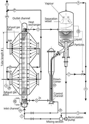
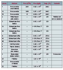
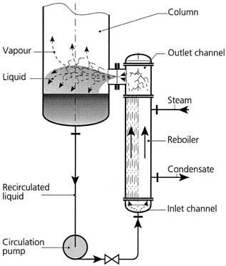
Figure 1 shows a simplified process diagram of a steam generator, while Table 1 lists the relevant process data. Among the typical characteristics of this installation are the fact that the exhaust gas flow is split into two streams crossing the heat exchange tube bundle from opposite sides, plus the tube pattern which results in rectangular inlet and outlet channels. This design has been chosen to minimise the pressure drop and consequently the power loss of the gas turbine, the performance of which is sensitive to back pressure. Furthermore, this design has the advantage of an almost equal heat load being applied to each tube. The discharge of the blow-down into the injection hole together with the produced steam is also characteristic of this installation. It is very important that the undissolved solids produced in the system consist of relatively fine crystals which flow easily with the blow-down. This can be achieved by mixing the cold feed with the recirculated flow in a proprietary mixing section. Moreover, the formation of deposits on the walls of vessels and piping should be minimised, so that such deposits cannot break off in large pieces during operation, causing problems in the circulation of the flow through the exchanger. Very often, large deposits are the result of a disturbance in the operating conditions and can subsequently cause thermal shock. Various measures have been incorporated in the design of the steam generator to prevent the presence of large, loose pieces of deposits in the circulating liquid flow.
The results of the study are so promising that two major oil companies in the United States have decided to build pilot plants as the next step in the realisation of full-size steam generators employing self-cleaning technology with evaporation in the tubes. Steam with a pressure of 45 bar will be produced in one of the pilot plants, while in the other the steam pressure will be as high as 100 bar.
Very large heat exchange systems
Self-cleaning heat exchangers are now also being considered for new plants to be built in coastal areas such as the Caribbean and the Middle East, where there is little or no fresh water available for cooling services. Seawater theoretically makes the best heat sink in these locations. However, seawater heat exchangers suffer from a combination of very severe biological fouling and sedimentation fouling.
An excellent solution for this dilemma is to use the self-cleaning heat exchanger as a closed-loop cooler. The main objective of using closed-loop coolers is to avoid the use of seawater in a large number of plant coolers. As a result, the problems of corrosion and fouling are concentrated in a few very large, seawater-cooled, closed-loop coolers, which are responsible for cooling the closed-loop fluid used throughout the plant. Normally, this closed- loop fluid is conditioned water, which does not foul or corrode the shell side of either the closed-loop coolers or the exchangers in the plant. Neither does it foul or corrode the connecting piping, the pumps, the valves, etc. in the clean coolant circuit between the closed-loop coolers and the exchangers in the plant.
Self-cleaning, closed-loop coolers have the advantage that they completely eliminate the fouling problems caused by seawater due to the circulation of the cleaning particles through the tubes. Eliminating fouling lowers the risk of corrosion and makes it possible to consider the use of cheaper materials, e.g. duplex instead of titanium.
For this particular application, the process conditions are:
• heat load: 460 MW,
• closed-loop water flow : 40 000 m3/h,
• closed-loop water temperature in/out: 43.9/33.9 °C,
• seawater flow:
80 000 m3/h,
• seawater temperature in/out: 26.7/
31.7 °C.
For environmental reasons, the temperature increase of the seawater has been restricted to 5 °C, which explains the rather large seawater flow.
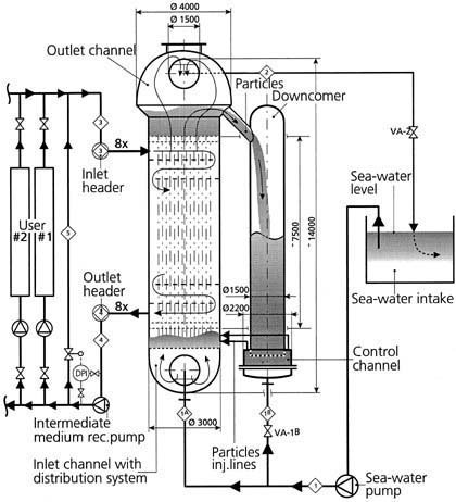
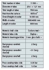
Four parallel coolers were selected for handling this thermal duty. A simplified process diagram and the configuration of one of these coolers are shown in Figure 3. Table 2 lists the specific mechanical design parameters.
The pressure drop on the tube side due to the bed weight of the cleaning particles and the hydraulic losses is only 0.35 bar. The position of the outlet channel of the cooler above the level of the sea would create absolute vacuum conditions in the outlet channel and a breakdown in the flow due to vapour lock. However, it is also possible to place the cooler in a pit at a depth of 6 m below sea level. This will prevent vapour lock while still allowing the cooler to be operated with its very low tube-side pressure drop. The large, flat walls of the shell of the large, rectangular-shaped cooler need strengthening. High-tensile strength tiers are used to reinforce the side walls by connecting them together. These tiers can pass through the tube bundle without influencing the shell-side film coefficient. The flat end walls of the cooler are reinforced by welding T-profiles onto their outside surfaces. The half cylindrical shape of the inlet and outlet channels guarantees sufficient strength without any need for additional reinforcement.
The inner tube surface is cleaned by a flow of 3 mm-diameter glass or ceramic balls through the tubes. Approximately 120 kg of glass or ceramic balls pass through each tube per hour. The cleaning particles are fed into the inlet channel from the bottom section of the downcomer, i.e. the control channel, through six injection lines with adjustable flows. The quantity of particles participating in the cleaning process can be influenced by varying the control flow through line 1B. This self-cleaning technology guarantees a perfectly clean surface for all tubes, even in case of the most severely fouling seawater and without any risk of the tubes becoming clogged. If conventional exchangers were employed, very severe biological fouling would occur in combination with serious sedimentation fouling, caused by the high concentration of sand and other particulates in the seawater.
In spite of the above-mentioned, severely fouling operating conditions, this self-cleaning, closed-loop cooler can operate continuously, i.e. year after year without intermediate cleaning, with an overall heat transfer coefficient of 2 000 W/m2K and possibly higher.
Low-cost reftrofit
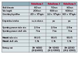
Existing, vertical, conventional reboilers which suffer from severe fouling can be revamped at low cost and integrated in a self-cleaning configuration. A typical example of a conventional reboiler installation that is suitable for revamping is shown in Figure 4.
Generally speaking, the requirements specified by plant management for the majority of revamps can be summarised as follows:
• The same process conditions should be maintained as in the original installa-tion, i.e. flow, liquid velocity in the tubes, evaporation in the tubes or suppressed evaporation in the tubes with flash evaporation into the column.
• The installed pumps should be used.
• The same connections should be used between the reboiler and the column.
• It must be possible to remove the cleaning particles during operation in case the revamp does not sufficiently reduce the fouling problem. In this case, the reboiler can continue to operate in the same way as before the retrofit.
• The revamp must be carried out within the available space.
One suggestion for a retrofitted reboiler that would be capable of meeting all the above requirements is shown in Figure 5. Many chemical companies have expressed an interest in revamping one or more of their fouling reboilers, as the cost of a retrofit is relatively low, as also follows from the examples listed in Table 3.
Klarex
Fax: ++31/33/
245 23 38
Further information
cpp-247
Unsere Webinar-Empfehlung

Der Webcast MTP und modulare Produktion bietet eine einzigartige Gelegenheit, mehr über die aktuellen Entwicklungen bei MTP und in der modularen Produktion zu erfahren.
Chemie- und Pharmaproduktion braucht mehr Flexibilität
In der heutigen sich schnell wandelnden Welt stehen…
Teilen: