The American Petrol Institute (API) draws up standards and guidelines for the technical plant, machinery and machine elements used in refineries and petrochemical installations. API Standard 682 lays down specifications for the mechanical seal and its buffer fluid system. An important part of this standard is the qualification test performed on the specified mechanical seals.
Günter Klier
API 682 was published in October 1994 as the first stand-alone standard for mechanical seals and buffer fluid systems capable of being applied in conjunction with pump specification API 610 (8th edition) for new machines or as an independent standard for existing machines. The philosophy behind API 682 is to guarantee the user-operator the following framework conditions:
• at least three years of continuous opera-tion,
• compliance with leakage regulations,
• a high degree of standardization of the mechanical seals used,
• verified and tested seal technologies.
To achieve these framework conditions the standard specifies the seal designs (type and arrangements), face materials and construction materials, supply systems, instrumentation, shipping preparations, qualification tests, acceptance tests and documentation.
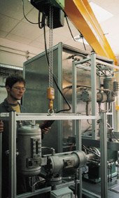
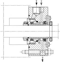
In order to provide proof of qualification for its API seal Burgmann created an extensive test program and invested around half a million marks in an API test stand (Fig. 1).
Purpose of the qualification test
API 682 is the first official and approved specification to describe both, qualification testing and prototype testing for mechanical seals. The seal series specified in API 682 can qualify for defined areas of application in refineries by passing these tests. In conjunction with the framework conditions, the qualification test guarantees that the end-user is supplied with mechanical seal systems of the highest reliability while providing a basis for mechanical seal optimization and further development.
It is not required to test all seal sizes in the media specified. Divergent test conditions can be agreed between the seal manufacturer and the customer should this be necessary for specific technical and project-related reasons.
Defined scope of testing
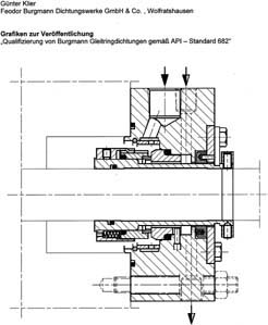
The specification requires every seal type (A, B and C) to be tested in every seal arrangement, single seal, pressureless and pressurized dual seal (Fig. 2). So as not to have to test every seal size, API 682 specifies tests with the diameter sizes 50 mm (2 inches) and 100 mm (4 inches) at a speed of 3600 min-1.
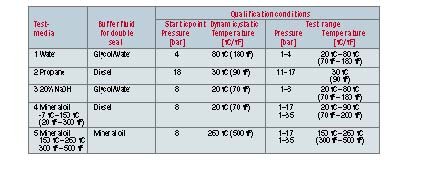
It is necessary furthermore to test each seal in the material combination „impregnated carbon graphite against reaction-bonded silicon carbide“ and „reaction-bonded silicon carbide running against silicon carbide“. Each seal version must also be tested with four different media, and three buffer or quench media are stipulated in addition for multiple seals (table).
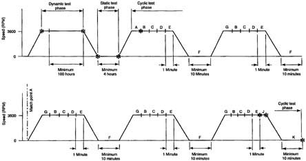
The test procedure breaks down into a dynamic phase, a static phase and a cycle phase of five cycles, with no dismantling of the seal allowed during the various phases. Leakage measurements have to be taken at those points marked with an asterisk in figure 3:
• phase 1: dynamic test at constant operating temperature (duration 100 h) and speed (n = 3600 min-1).
• phase 2: Static test at speed 0, same test parameters (duration 4 h) as in phase 1.
• phase 3: cycle test during which the operating temperature and pressure are varied and the mechanical seals are started and stopped. In the case of single seals with the test medium „volatile hydrocarbons“, the pressures have to be lowered to the respective vapour pressure (duration 30 to 40 h).
API test stand
The Burgmann API test stand is able to simulate all cases of application typical for refinery seals. Continuous measurement data acquisition of all the seal operating parameters, i.e. pressures up to 35 bar, speeds up to 3600 min-1 and temperatures up to 400 °C, is performed by a PC-based monitoring system, which also switches off the test stand automatically if the permissible limit values are violated.
The test stand has a performance of 152 kW. Buffer circuits of modular design enable fast changing of medium.
Tests are carried out in an explosion-protected test chamber. The latter is kept under slight vacuum and is ventilated continuously. It is also equipped with a gas alarm system, a splash guard and explosion-protected measuring sensors.
Test experience
The API 682 mechanical seals are based on the familiar and practice-proven DIN seals of series H75 and MFL 85. The API tests simulate the conditions in a pump in idealized form only, of course, the advantage being that they are performed with applica-tion related media and that their results are reproducible and comparable. The test results were positive. One of the main reasons for this is that the test parameters for the API test lie below the application limits of the company’s API seals.
A further aim of the test series was to cover the entire API 682 test range with a single seal (e.g. Type A, H75N/Dw), an exception having to be made with volatile hydrocarbons because in these cases there is a risk of the mechanical seals running dry and a somewhat modified sliding face geometry is required for larger shaft diameters.
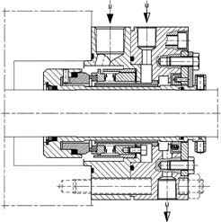
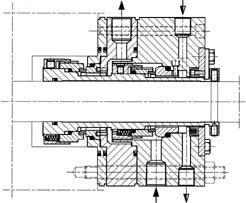
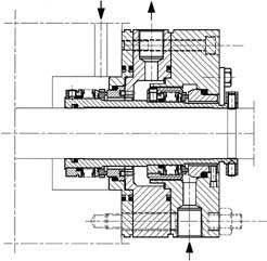
To comply with API 682, multiple seals (Fig. 4) have to be tested in accordance with the following criteria:
• test without an outboard seal and without buffer or quench fluid,
• test with an outboard seal and buffer fluid,
• test with an outboard seal and quench fluid and
• test under the maximum permissible internal pressure (e.g. type A, H 75K/Dw = 10 bar max.), whereby the seal is kept in continuous service for 120 hours.
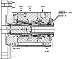
A further aim was to seal volatile hydrocarbons (e.g. propane) with a single seal of type A and B. The project „low emission seal“ was carried out for this purpose. Leakage requirements for the low emission seal lie below 50 ppm with a medium density of less than 0.4 kg l-1. To meet this requirement it is necessary to control the medium’s liquid-to-gas transition phase in the sealing gap in order to prevent dry running of the mechanical seal. The best results were achieved with the mechanical seal type H75N/Dw with a solid carbon seal face. The same seal type was used with a shaft diameter of 50 mm. In this case the solid carbon seal face is constructed with a back-up ring underneath the face – a design that enables a V-gap to be formed between the sliding faces in all operating phases. The liquid-to-gas phase transi-tion is thus shifted to the inner diameter of the sliding face. This seal produced very good test results in terms of wear rates, running profile and leakage rates, which lay far below the required 50 ppm limit.
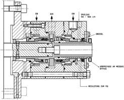
Good values were also achieved by the metal bellows seal tested (type B, MFL85N/Dw).The leakage rate with the 50 mm seal, for example, was approximately 32 ppm. A further aspect brought to light by this project was the very good effect exercised on the cooling of the sliding faces by multipoint injection in the flush. The uniform radial distribution of temperature around the circumference of the seal face and seat results in distortion-free sliding faces and guarantees a stable and low level of leakage in operation.
Measuring the leakage of volatile hydrocarbons
ESA describes three methods for measuring the leakage of volatile hydrocarbons (Fig. 5):
• EPA Method 21 (specified by API 682), the standard method, has been introduced by the US Ministry of the Environment. Measurements are taken with a snifter. The central component in this case is a flame ionization detector. The difference between the background charge and the leakage is measured. Leakage is determined in ppm.
• Method 21 is the simplest measurement method and may be put to the most universal use. It was employed to measure the leakage on all Burgmann tests with volatile hydrocarbons.
• The bagging method requires the greatest outlay for taking a measurement. In this case the entire pump is packed and flushed with a carrier gas. The charge can be measured with a flame ionization detector.
• Flushing gas method, a fast and reliable method, is a combination of the bagging method and Method 21.
Ensuring high reliability
Clearly, there is no technical necessity for all the test combinations. It is questionable whether a metal bellows seal of type B has to be tested in water or whether an O-ring seal of type A has to be run at an operating temperature of 260 °C. References already exist for the majority of test runs in respect of the specified test media. In many of these references the operating parameters lie above the limits specified by API. API 682 qualifica-tion has to be proven by the mechanical seal manufacturer himself. It is his responsibility to carry out the tests and document the results correctly. At least the most important qualification tests should be carried out by an independent test commission in order to guarantee equal opportunity among seal suppliers.
With its underlying philosophy, API Standard 682 ensures the user-operator a high level of reliability and good possibilities of standardization for the mechanical seals he uses. All manufacturers have no option but to intensify their development work with a view to prolonging seal life and minimizing seal leakage. A viable alternative for surpassing these framework conditions is to use gas-lubricated mechanical seals in refineries and petrochemicals installations.
Burgmann
Fax: ++49/8171/23-1095
Further information cpp-203
Unsere Webinar-Empfehlung
Die Websession „Wasserstoff in der Chemie – Anlagen, Komponenten, Dienstleistungen“ (hier als Webcast abrufbar) zeigt technische Lösungen auf, die die Herstellung und Handhabung von Wasserstoff in der chemischen Industrie sicher machen und wirtschaftlich gestalten.
Ob effizienter…
Teilen: