

The use of pervaporation and vapor permea-tion processes in the chemical industry is still in its infancy. Pervaporation has now proved its suitability for end-of-pipe applications such as solvent recovery, and increased use in more critical applications such as separating reaction mixtures is anticipated. New membranes are being developed to expand the horizons still further.
In most membrane processes the bulk component is purified by passing it through a membrane which holds back the minor component. The membrane acts rather like a filter or strainer. Processes such as ultra, micro and nanofiltration work in this manner, using porous membranes. Reverse osmosis is similar, but uses non-porous membranes. Pervaporation and vapor permeation processes are used in the reverse situation, i.e. when the non-porous membrane is preferentially permeated by the minor component. The bulk fluid is held back by the membrane. To obtain a pure product stream in this situation, almost all of the permeating component has to pass through the membrane. This is why pervaporation and vapor permeation generate a driving force by applying a vacuum to the permeate side. Very high pressure ratios result, so that removal of the minor component is maximized without an excessive pressure difference across the membrane. Undue mechanical stresses on the membrane and equipment are avoided.
As substances which permeate non-porous membranes are reasonably volatile, the application of a vacuum always causes the permeate to be desorbed from the membrane in the vapor state. This is the reason for the term pervaporation if the feed to the membrane is liquid, since the contaminant appears to evaporate through the membrane. If the feed is vapor or a gas/vapor mixture, the process is called vapor permeation.
Currently, the best-performing industrial membranes permeate water in preference to other components. This is why filtration and RO processes are typically used to purify water, whereas pervaporation and vapor permeation are used typically but not exclusively to remove water from organics.
Pervaporation and vapor-permeation plant design
Pervaporation and vapor-permeation plants are relatively simply designed. Membranes are generally packed in plate and frame modules, because these can be assembled without the use of adhesives. Such units are compatible with all chemicals which can be handled in stainless steel equipment. The most successful approach is to install these complete modules in vacuum vessels, so that the gasketed joints are not also responsible for isolating the process fluid.
In large plants permeate is usually condensed under vacuum. Here the vacuum pump is only sized to remove non-condensables, and the pervaporation process itself is thermally driven and very energy efficient.
Continuous pervaporation plants
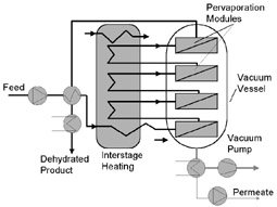
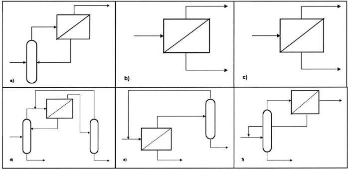
Most pervaporation plants operate in continuous mode (Fig. 1). Liquid feed is preheated in a recuperator and feed heater and then passes through a series of pervaporation modules installed inside one or more vacuum vessels. Water permeates the membranes, is condensed inside the vacuum vessel and is periodically pumped out. A vacuum pump is installed to remove non-condensables. Solvent is continually dehydrated as it passes through the series of membrane modules.
Small-capacity batch pervaporation units
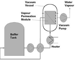
Pervaporation plants are also available for operation in batch mode (Fig. 2). These batch units are simpler and more flexible than continuous pervaporation plants. With capacities up to a few hundred kg/h, this simplicity results in considerable cost savings.
Batch pervaporation plants operate by continuously circulating the contents of a buffer tank over a bank of pervaporation membranes. Retentate contains less water and is continuously returned to the buffer tank. Thus the contents of the buffer tank are progressively purified over a period of several hours or days. Such plants are simple because no interstage heating is required. The pump-around rate is set high, so that the fraction to be pervaporated per pass and the pervaporative cooling effect are small.
Vapor permeation plants
Vapor permeation is a more modern technique offering advantages in a number of situations. The basic process is similar to pervaporation and uses the same membranes, however:
• The feed is totally evaporated and contacts the membrane as a saturated vapor.
• Since all streams are in the vapor phase there is no phase change and hence no pervaporative cooling. Interstage heating is not required.
• The plant is simpler and costs less than a continuous pervaporation plant. However, if the feed is liquid it has to be evaporated before contacting the membranes.
Vapor permeation is particularly attractive if the feed is obtained overhead from a distillation column. The two systems can be coupled by treating overhead vapor directly in the vapor permeation plant (Fig. 3). Vapor permeation units are also recommended when small amounts of dissolved or suspended solids are present in the feed. Evaporating the feed allows solids to be completely removed by a liquid blowdown from the evaporator.
Applications Separation of azeotropes
A large number of alcohols, esters, ethers and other volatile compounds azeotrope with water. Figure 4 shows VLE data for a selection of materials that are currently dehydrated using pervaporation or vapor permeation. In many cases pervaporation alone is the most economical approach. Combinations with distillation can be attractive how-ever if the feed is dilute or if the product can be distilled above the azeotrope. Figure 5 indicates where different combinations can be applied.
Debottlenecking entrainer distillation systems
Pervaporation/vapor permeation is prefer-able for new stand-alone azeotrope separa-tion plants. However, old plants with entrainer distillation systems can be effectively debottlenecked using pervaporation/vapor permeation.
Normally the rectification column will be operating to give a product as close to the azeotrope as possible, running with a high reflux. To debottleneck the system, reflux in the rectification column is reduced, giving more overhead product, but with a higher water content. This water is removed by the pervaporation unit, also relieving the load on the subsequent entrainer column. Both columns can then achieve a significant capacity increase. The pervaporation unit required for debottlenecking is relatively small since the driving force for water permeation is high.
Debottlenecking pinched distillations
Distillation processes are driven by volatility differences. If these volatility differences are small, or become small under certain conditions, then columns need to operate with high reflux to achieve the desired separation. Since pervaporation/vapor permeation processes separate irrespective of volatility differences, they can be used very effectively to debottleneck pinched distillations.
Let us consider for example, the acetone/water system. Acetone is enriched in the vapor phase at low concentrations, so that stripping acetone from water is easy. This is not the case with high concentrations. Complete dehydration of acetone is difficult. Adding a pervaporation/vapor permeation unit can yield spectacular results.
Continuous water removal from esterification reactions
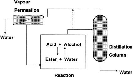
Continuous removal of by-product water from the esterification reaction mixtures shifts the equilibrium in favour of higher ester conversion – removal of all water will result in total conversion of reactants. How-ever water removal from such mixtures is not easy. Simple evaporation, for example, can also remove the other low-boiling compounds, e.g. the alcohol and the ester, from the system as well. Complete water removal by distillation is difficult due to azeotrope formation. Pervaporation/vapor permeation processes are ideal for continuously removing water from esterification reactions. In Figure 6 the evaporated reaction mixture is continuously distilled to the azeotrope. Column overhead vapor, close to the azeotropic composition, is passed through a vapor permeation unit in order to continuously remove water down to very low levels, thus driving the reaction to completion.
Methanol removal
Not only water can be permeated out of reaction products. Polymer membranes are now available which permeate methanol preferentially to other organics. One industrial plant which is already operating continuously removes methanol from a reaction product using a combination of distillation and vapor permeation. Plants have also been engi-neered which use these membranes to separate methanol from ethyl acetate, THF and a number of other compounds which azeo-trope with methanol.
Sulzer Chemtech
Fax: ++49/6821/792-50
Further information cpp-234
Unsere Webinar-Empfehlung
Der Webcast MTP und modulare Produktion bietet eine einzigartige Gelegenheit, mehr über die aktuellen Entwicklungen bei MTP und in der modularen Produktion zu erfahren.
Chemie- und Pharmaproduktion braucht mehr Flexibilität
In der heutigen sich schnell wandelnden Welt stehen…
Teilen: