An essential part of equipment safety is the fail-safe position to be maintained if a fire breaks out. In the case of pneumatic linear actuators, the fail-safe position must be assumed and maintained if the air supply fails or the diaphragm ruptures.
Walter Schneider
Normally, springs are used to perform this task. They force the valve to move to the fail-safe position if dangerous situations arise or damage occurs. The springs act against the pressure of the process medium to move the valve to the fail-safe position if the air supply fails, and then keep it in this position.
If a fire breaks out, the fail-safe position of the pneumatic actuator will be negatively affected. The high temperatures cause the springs to lose their force. As time goes by and the temperature rises, the springs are no longer able to maintain the valve in its fail-safe position. In the „fail-close“ position of the actuator springs, it will not be possible to prevent the leakage rate from increasing.
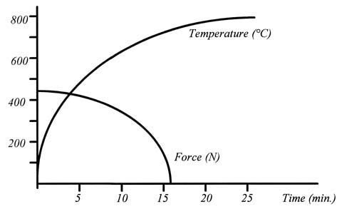
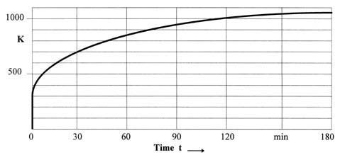
Figure 2 shows how a preloaded spring loses its force under the influence of temperature.
Soon after the fire breaks out, the spring force decreases abruptly. As a result, its ability to keep the valve in the fail-safe position during the fire will be lost within a short period.
The loss of rigidity and the considerable reduction in the force are caused by re-crystallisation processes within the material structure of the spring.
The use of conventional fire protection systems, such as coatings, does not result in any significant advantages, since springs are moving components and subject to dynamic stress. Coatings are likewise unable to sufficiently retard the loss of force.
Safety cartridges
The problems described above were solved by developing a thermostatic system. This passive system was supposed to recognise non-typical temperature rises and respond to them actively. An extremely simple element, a cartridge, was used to perform this task.
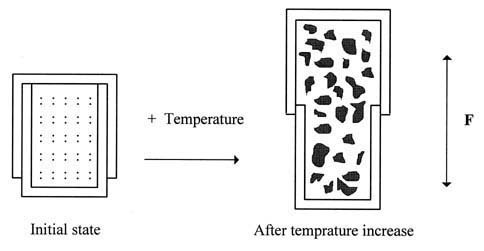
This cartridge consists of two cylinders sliding freely inside each other. It is filled with intumescent material, which can be regulated in such a way that it determines the release temperature within certain limits plus, of course, the increase in the force it exerts.
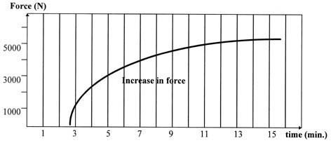
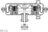
The cartridge consists of a two-part cylindrical case. The en-closed cylindrical chamber contains the intumescent material. This material is regulated in a special way to ensure that the cartridge is activated before the diaphragm of the pneumatic actuator is destroyed. The increase in volume causes the cylinders to move in opposite directions. During this process, considerable forces are produced. The operating direction of the cylinders corresponds to that of the springs, so that their gradual loss in strength is counteracted. When installed in actuators with safety equipment, these patented cartridges ensure decreasing spring force compen-sation.
The safety cartridge is heated according to the standard temperature curve, in which the change in temperature over time is plotted in accordance with DIN 4102, Part 8.
The design of this irreversibly operating cartridge is simple, allowing it to be retrofitted in pneumatic actuators that are already installed.
To do so, the safety cartridge must be positioned in the centre of the actuator springs. The mounting position of the pneumatic actuator is not important, as the cartridge can always perform its task of closing the valve in the event of a fire.
The selected overall length of the cartridge does not affect the travel or operating range of the springs at standard ambient temperatures. Only in the event of a fire does the cartridge become effective by reacting to the unusually high temperatures.
Simulation of a fire
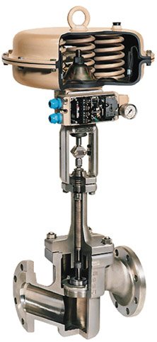
A control valve equipped with a safety cartridge of this kind was subjected to a simulated fire.
Technical data of the control valve used for the simulation:
• Valve: type 3241, nom. size DN 25, nom. pressure PN 40,
characteristic: equal percentage,
valve plug: lapped-in-metal,
plug material: Cr steel, WN 1.4006,
seat material: Cr steel, WN 1.4006,
body material: GS-C 25, WN 1.0619.
• Actuator: type 3271 pneumatic actuator,
effective diaphragm area: 350 cm²,
actuator stem extending,
signal pressure range: 0.6 to 3 bar,
material: St 1203,
diaphragm: NBR with polyester fabric.
The test aimed to maintain the tightness of the valve over a period of at least 30 minutes, with a constant system pressure acting on it. The time span is based on the specifications contained in BSI 6755/2.
The test valve described above was heated in a test room according to the standard temperature curve. The pneumatic actuator was equipped with six cartridges installed in the actuator spring assemblies. The valve contained water. During the heating phase, steam was produced. A pressure regulator installed outside the test room maintained a constant system pressure of 30 bar. Prior to starting the test, a pump had been used to produce this pressure. Downstream of the seat/plug restriction area, the valve was open to the atmosphere.
The temperature in the test room and in the pneumatic actuator was measured by means of thermocouples. The temperature increase over time in the test room and in the pneumatic actuator corresponded to the standard temperature curve (Fig. 5). The system pressure of 30 bar in the valve upstream of the seat re-mained constant during the entire test proce-dure. As was to be expected, the rubber diaphragm was completely destroyed at the end of the test. With the exception of the springs, none of the metallic components showed any visible signs of damage or deformation.
The objective of ensuring tight shut-off against the pressure of 30 bar that prevailed throughout the test and during the high temperatures of the fire was fulfilled throughout the entire period of heat supply.
Reversible operating direction
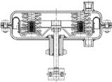
In addition to the safety cartridges, there are other solutions that can be integrated in the pneumatic actuator for safety purposes. It is possible to use a preloaded spring assembly which is released at a settable temperature to oppose the standard fail-safe position. This patented method includes preloaded spring discs which act in opposition to the standard actuator springs. The spring discs are bound by a solder strip. The type of solder determines the temperature at which the spring discs are released to act as an additional safety device. When the spring discs are released, the standard fail-safe action is reversed. The solder joint is extremely stable under many different operating conditions, such as permanently high ambient temperatures.
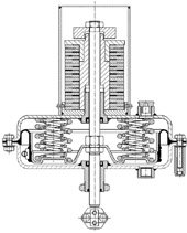
A pneumatic actuator equipped with this kind of safety device is shown in the sec-tional drawing in Figure 7.
Summary
The safety device has a simple structure, enabling the pneumatic control valve either to assume a fail-safe position or to reverse this fail-safe position if a fire breaks out. Pneumatic control valves can now be used in applications which were previously never considered possible.
Compared to pneumatic control valves with standard fail-safe action, actuators equipped with these innovative safety devices are able to maintain the fail-safe position over an longer period of time when exposed to fire.
The safety cartridge filled with intumescent material plays a crucial role in this safety system. Thanks to these cartridges, the valve trim remains effective even at the extremely high temperatures that occur in the event of a fire, thus preventing leakage of hazardous media. The cartridges compensate for the loss of spring force, which under less extreme conditions guarantees fail-safe action.
Another advantage of the safety device is its cost-effectiveness compared to other types of safety equipment in use. Since the safety cartridges can replace more complex and hence more expensive safety devices, they will prove to be an attractive solution in view of the increasing pressure of costs.
Alternatively, conventional fail-safe action can be reversed if a fire breaks out. Releasing preloaded and bound spring discs reverses the direction of the standard fail-safe action of pneumatic actuators. A further important aspect of this innovative method is the fact that the temperature range in which the springs are released can be adjusted as needed.
Samson
Fax: 0049/69/4009507
Further information cpp-245
Unsere Webinar-Empfehlung

Die Websession „Wasserstoff in der Chemie – Anlagen, Komponenten, Dienstleistungen“ (hier als Webcast abrufbar) zeigt technische Lösungen auf, die die Herstellung und Handhabung von Wasserstoff in der chemischen Industrie sicher machen und wirtschaftlich gestalten.
Ob effizienter…
Teilen: