Commerce and industry alike are calling for economical systems to meet the emission limits laid down by law. Katox systems can meet these requirements for a broad range of applications.
Gunther Kuwert, Ralf Sattler
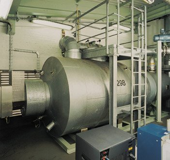
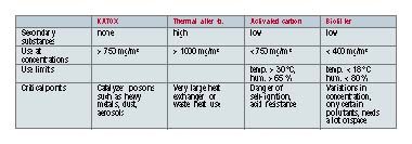
Katox plants, as shown in Figure 1, can remove fluorocarbons and chloro-fluorocarbons at low temperatures with conversion rates of over 99.8%. The most important requirements for designing these plants were the development of suitable catalysts and the refinement of the appropriate equipment technology. Secondary problems caused by the formation of additional residual materials which are difficult to dispose of (activated carbon) or additional pollutants (NOx, dioxins produced by thermal after-burning) do not occur. Table 1 gives an overview of the characteristics of the Katox process in comparison with thermal after-burning, activated carbon absorp-tion and biofiltration.
Process technology
The principle of catalytic exhaust-gas purification is based on the oxidation of organic pollutants on the catalyst surface of CO2 and H20. With halogenised pollutants, hydrogen halides are created as further by-products of this reaction. The catalyst causes the reaction temperature to fall and emerges from the reaction unchanged. The aggressive hydrogen halides are rinsed out and neutralised in a further stage of the process.
Catalyst
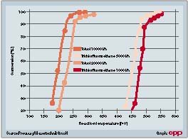
CFC Katox plants use specially developed bearer catalysts which have highly active platinum and palladium catalytic components on the surface. Honeycomb or monolithic catalysts are used as the carriers. Different diameters or cell densities affect the geometric surface and the pressure loss. These catalysts are extremely resistant to catalyst poisons such as chlorine or fluorine. Other positive features include the excellent thermal and mechanical resistance. The efficiency of the catalyst is given as the space velocity (quantity of waste gas that can be moved across 1 m3 of catalyst in one hour) and is dependent on the pollutant and temperature. At each space velocity, the catalyst has a particular turnover behaviour (Fig. 2).
Design of the plant
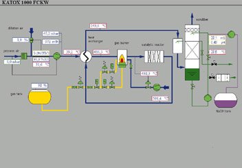
Figure 3 shows how a CFC Katox plant is constructed. It consists of:
• A compactor to compensate for pressure loss,
• a heat exchanger for heat recovery,
• a gas burner to heat up to reaction temperature,
• the reactor with the precious metal catalyst,
• a gas purifier with quench,
• the instrumentation and control apparatus with PLC and process control system.
Most of the equipment is made of 1.4571 fine steel. Depending on requirements and customer wishes, it can also be built using HII, 1.4539, 1.4541, 1.4876 or 1.4878 materials, with resistance to pressures ranging from normal to explosion force.
Dimensions and operation
The size of such plants is determined by the pollutants and the required clean-gas values as defined in the TA Luft clean air regula-tions, keeping investment and operating costs in mind. If the reaction products are HCI and HF, which produce hydrochloric and hydrofluoric acid, the choice of material is crucial.
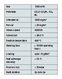
On this basis, the optimum operating conditions were determined and the plant (Fig. 3) designed as shown in Table 2.
During operation, the waste gas containing pollutants is drawn out by means of a compactor and preheated in the jacket area of the downstream shell-and-tube heat exchanger. The exhaust air is then heated if necessary with a gas burner to the required reaction temperature at the catalyst, which is around 490 °C. In the reactor, the pollutants are transformed on the surface of the catalyst. The waste air now flows through the tube area of the heat exchanger, where it loses much of its heat. Special design measures avoid dead spaces in the flow, and thus condensation of HCl and HF in the waste air. After the heat exchanger, the waste air – which is still hot – reaches the PTFE high-performance quench, where it is cooled to less than 50 °C. In the counter-flow gas purifier, HCl and HF are rinsed out of the exhaust air flow. The wash liquid which is used is recirculated and neutralised with caustic soda. The salts that are formed (NaCl, NaF) are discharged with the wash liquid, depending on the concentration (conductivity 100 µS). This gas purification ensures that the limit values specified for HCl and HF in TA Luft are complied with.
Advantages of Katox technology:
• Selective catalytic oxidation prevents undesirable reactions.
• No secondary substances are created which have to be treated or tested (as with solvent recovery).
• Even carbon monoxide and nitrogen oxides only occur in small quantities.
• The tough, functional technology is easy to install in existing systems (end of pipe) and does not take up much space.
• The high level of heat recovery and low pressure loss keep operating costs down.
Practical experience
After two years in operation, no appreciable corrosion of the plant or deactivation of the catalyst was found. The conversion rate is over 99.8% and the limit values laid down in the clean air regulations (TA Luft) are satisfied easily.
Katox plants thus represent an economical and technically mature solution for treating exhaust gases containing CFCs. In addition to CFCs, other hydrocarbons such as petrol, alcohols, aromatic hydrocarbons, organic acids, odour substances etc. can also be converted. Autothermal operation, in other words without additional heating, is possible with these substances at concentrations as low as 2 to 3 g/m3.
Preussag Wassertechnik
Fax: ++49/6251/980498
Further information cpp-207
Unsere Webinar-Empfehlung
Die Websession „Wasserstoff in der Chemie – Anlagen, Komponenten, Dienstleistungen“ (hier als Webcast abrufbar) zeigt technische Lösungen auf, die die Herstellung und Handhabung von Wasserstoff in der chemischen Industrie sicher machen und wirtschaftlich gestalten.
Ob effizienter…
Teilen: