


Flurosic(r) shell-and-tube heat exchangers made with silicon carbide have a universal chemical resistance and offer very good thermal conductivity as well as – thanks to the special design of the tube sheets – excellent mechanical properties.
The design of this shell-and-tube heat exchanger allows the unit to be operated in corrosive media, because silicon carbide has been chosen as the material for the heat transfer. As a comparable alternative to exotic alloys, fragile glass or highly expensive materials, silicon carbide offers universal chemical resistance combined with relatively good thermal conductivity. The advantages offered by sili-con carbide with regard to thermal conductivity are heightened by the tube wall thicknesses of just 1.5 or 2.2 mm, leading to excellent u-values. The u-values are better than those of most other materials including graphite. Even with such very thin walls, every single tube is tested with a pressure of 180 bar before being installed in the heat exchanger unit (Fig. 1).
Anzeige

In einer Ära, in der die Chemieindustrie mit den Herausforderungen des Klimawandels und der Notwendigkeit einer nachhaltigen Entwicklung konfrontiert ist...
Only alpha-sintered silicon carbide is used for the heat exchanger. Unlike alternative sintering processes, the SiC does not contain any free silicon that could react with other chemicals. SiC contains free silicon, for example, and is often used in mechanical seals, where it exhibits only limited chemical resistance.
It should therefore not be compared to the alpha-sintered SiC.
SiC has been used in heat transfer processes for more than 2 million hours to date. There has not been a single report of any chemical reaction during this time. The material is extremely hard and as such erosion-resistant (approved by KTW for drinking water applications). In addition to being suitable for high-purity applications the hard surface allows high velocities that further improve the thermal performance.
Design of the shell-and-tube heat exchanger
The design of the tube sheet has been newly developed to obtain the maximum possible operational safety. The tube sheets consist of two PFA-encapsulated steel plates (Fig. 2) that are fixed together by screws. As a result of the force between the two sheets an individual O-ring is pressed tightly around every single tube, providing a reliable seal. The O-ring sealing method obviates the need for welding, which may be the cause of mal-functions. The PFA cover of the tube sheets has no mechanical function at all. The stress from different thermal extensions in the system is therefore absorbed by the steel and not by the plastics. The result is a mechanically resistant heat exchanger that handles shocks such as changes in temperature or pressure with continuing operational safety.
The design of the tube sheets allows individual tubes to be replaced in the field by the owner’s staff. The sheets can be removed for this purpose with the help of a special tool set (Fig. 3). This is not usually possible if welded constructions are used. Maintenance, cleaning and general inspections also involve shorter down times.
Field test
A batch-type distillation unit in a pharmaceutical plant includes a regularly used device for distilling acetone and water from a mixture of acetone, water and butyl alcohol (see Fig. 5 for a schematic drawing ) A graphite heat exchanger and the SiC heat exchanger are installed in parallel to facilitate condensation. The media is fed through a main pipe and a secondary pipe to the condensers. Whereas the graphite unit offers a heat exchange area of 11.5 m² and a cooling water supply of 4.5 m³/h, the Flurosic achieves 1.3 m² and a flow of 1.1 m³/h. The heat exchangers were observed during three tests. The flow rate of the cooling water was used as the basis for the final calculation. It was chosen because all the data, such as the flow rate and the temperatures, has been measured. Owing to the varying incoming flows, heat exchange areas and discontinuous operation, the ratio between the heat flow and the exchange area was represented as a code number in the final results ( kW/m²) (Fig. 4).
The evaluation shows that, with comparable thermal conductivity data, the SiC heat exchanger has a significantly better heat flow density than the thick-walled graphite unit. A factor of 2.27 can be computed for the difference. So far, however, only three tests have been carried out. A factor of 2.27 for the difference in the heat transfer per square meter for a medium with proven equivalent thermal conductivity is an excellent result for the SiC heat exchanger; how-ever, it needs to be interpreted in a little more detail. The surprisingly good result can be explained by the well-designed flow through the apparatus and the reduced wall thickness. At the same time no further cooling of the distillate is observed, in contrast with the graphite unit, which in this case is not required anyway. In addition, the surface properties of the smooth SiC improve the heat transfer performance.
As the test series shows, the Flurosic is highly recommended for installation as a condenser in universal distillation units such as this. The required heat exchange area can be reduced by as much as 10 to 30% compared to the graphite unit. This means that the end user is able to reduce the costs for space, pipes, maintenance and cleaning.
Areas of application
Besides operating as a condenser for universal distillation processes, the Flurosic SiC heat exchanger is recommended for all applications where highly corrosive media must be treated thermally. The media may be liquid or gaseous. The SiC shell-and-tube heat exchanger can be used as an evaporator, falling-film evaporator, isothermal tube reactor or universal apparatus.
Its main technical data is as follows:
• Temperature range: -50 °C to +180 °C,
• Operating pressure: -1 bar to + 8 bar,
• U-value for liquid-liquid heat transfer: 700 to 2,600 W/m²K,
• U-value for condensation processes: 1,000 to 4,000 W/m²K.
Various materials can be used for the shell, the bonnet and the gaskets, which can be integrated into the heat exchanger according to requirements, due to the modular design. There are shells made of stainless steel without a PTFE lining, for example, glass-lined or glass shells for vacuum applications. The same naturally holds true for the bonnets. The length of the bundles and the dimensions of the shells can be combined in many configurations, which allows us to offer numerous different heat exchange areas from as little as 0.2 m² to 30 m² or more.
Any bundle orientation is possible when it is integrated in the process. The unit can be installed vertically, horizontally or at any angle inbetween. The computer-aided process design for every single unit includes a vibra-tion analysis.
Dr. Schnabel
Fax: ++49/6431/23570
Further information cpp-255
Unsere Whitepaper-Empfehlung
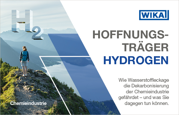
Wasserstoff gilt als Schlüssel für die Dekarbonisierung der Chemieindustrie. Doch die Nutzung des vermeintlichen Hoffnungsträgers Hydrogen birgt auch Gefahren und stellt die Branche vor neue Herausforderungen, die das gratis Whitepaper „H2 wie Hoffnungsträger?“ näher für Sie…
Teilen: